1. Contamination Fault: The "Instantaneous Collapse" of Insulation Strength
Contamination faults are the most common and hazardous type in 35kV systems, essentially representing a rapid loss of surface insulation strength.
Fault Patterns and Process Analysis
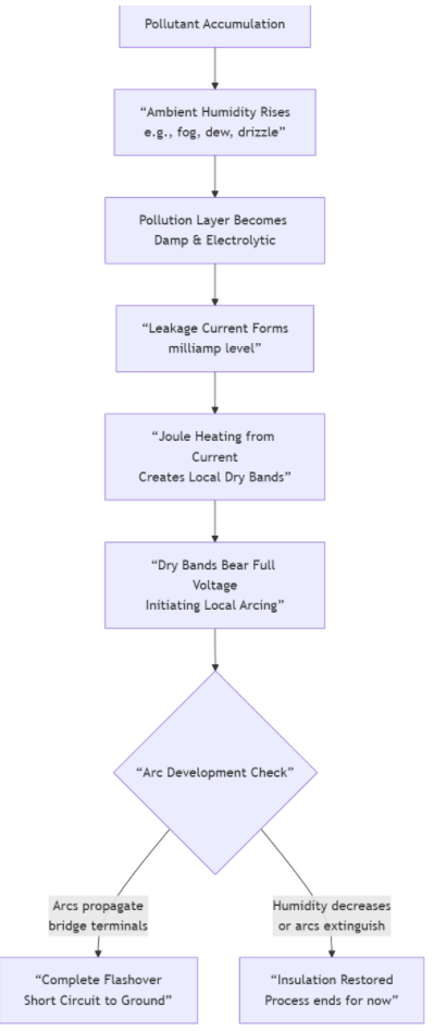
The development of a contamination fault is a typical gradual process. The complete path from pollutant accumulation to final flashover is illustrated below:

Corresponding Field Phenomena and Test Data:
Visual Patterns:
Flashover Path: Porcelain insulator surfaces show black, dendritic, or ribbon-like carbonized burn marks, typically bridging the two Terminals.
Corrosion: The steel pin and cap of composite insulators show severe corrosion; nearby silicone rubber may be chalky, whitened, or even carbonized.
Test Data:
Insulation Resistance: Measured with a megger, values may be below 300 MΩ (warning level), approaching zero in severe cases.
Infrared Thermography: Detects uneven temperature distribution on the insulator surface in humid conditions, with local hot spots (areas of concentrated leakage current).
Root Cause Diagnosis and Prevention Strategies
Diagnosis Keys: Faults frequently occur during humid conditions like early morning, fog, or drizzle; the fault location is often near pollution sources like industrial areas, coastlines, or farmland.
Prevention Strategies:
1. Precise Selection: Choose insulators with sufficient creepage distance based on the contamination level (e.g., Class d/IV), or directly use anti-fog type insulators (e.g., alternating shed/DC type).
2. Proactive Maintenance: Perform live-line or de-energized cleaning before the contamination season; apply Room Temperature Vulcanizing (RTV) silicone coating to exploit its superior hydrophobicity and prevent continuous water film formation.
3. Condition Monitoring: Install online leakage current monitoring devices to grasp the insulator's operating state in real time and achieve early warning.
---
2. Aging Fault: The "Gradual Degradation" of Performance
Aging is the irreversible deterioration of material properties under long-term electrical, thermal, mechanical, and environmental stress.
Fault Patterns and Process Analysis
Visual Patterns:
Porcelain Insulators:
Glaze Deterioration: The glaze loses luster, develops crazing cracks; in severe cases, the porcelain absorbs moisture internally.
Cement Degradation: The cement between the metal fittings and porcelain cracks, crumbles, or spalls, leading to a severe drop in electromechanical performance.
Composite Insulators (Silicone Rubber):
Loss of Hydrophobicity: The housing and sheds become hard, brittle, chalky, and cracked; the contact angle decreases.
Electrical Erosion: Severe arcing damage near the high-voltage end fitting creates pits, perforations, potentially exposing the core rod.
Core Rod Brittle Fracture: If sealing fails and moisture ingresses, the core rod can undergo "brittle fracture" under acid and stress, characterized by a clean break.
Root Cause Diagnosis and Prevention Strategies
Diagnosis Keys:
Infrared Thermography: Aged composite insulators may show overall or local temperature rise due to increased leakage current.
Hydrophobicity Check: Using the spray method (HC method), a persistent drop to HC4 or worse indicates severe aging.
Ultrasonic Testing: Detects internal cracks in porcelain insulators and defects in the core rod of composite insulators.
Prevention Strategies:
1. Regular Sampling: Establish a life-cycle record for insulators, conducting regular visual inspections, hydrophobicity tests, and mechanical load tests.
2. Timely Replacement: Proactively replace insulators that have reached their design life (typically 25-30 years for composite) or show severe performance degradation.
3. Quality Control: Source products from reliable manufacturers with verified sealing performance.
---
3. External Damage Fault: The "Sudden Failure" of Mechanical Structure
Fault Patterns and Process Analysis
Visual Patterns:
Gunshot/Impact: Localized holes or shattering; torn sheds and exposed or broken core rods in composite insulators.
Bird-Related Damage: Bird streamers causing flashover leave linear burn marks; large birds defecating on cross-arms can cause flashovers.
Construction Damage: Foreign objects (e.g., plastic film, kite string) on conductors or fittings; mechanical scrape marks on the insulator itself.
Ice Damage: In heavy ice areas, thick ice accumulation or non-synchronous ice shedding creating huge unbalanced mechanical loads can cause insulator strings to twist, collide, or even snap.
Root Cause Diagnosis and Prevention Strategies
Diagnosis Keys: Sudden fault occurrence, often correlated with specific events (e.g., high winds, construction, hunting); the location and damage morphology show clear signs of mechanical impact.
Prevention Strategies:
1. Physical Protection: Install anti-bird spikes, bird diverters; add warning markers near insulators; monitor and patrol key line corridors.
2. Enhanced Design: Use tension structures or V-strings in prone areas to improve mechanical stability.
3. Awareness & Law Enforcement: Strengthen publicity on power facility protection and collaborate with law enforcement to combat vandalism.
---
Summary: Diagnostic Flow and Maintenance Recommendations
When a 35kV Insulator fault is discovered, follow this process for preliminary diagnosis:
1. Visual Inspection: Check for obvious flashover marks, cracks, electrical erosion, foreign objects, etc.
2. Environmental Context: What was the weather during and before the fault? Were there activities like construction or hunting nearby?
3. Data Measurement: Measure insulation resistance, perform infrared thermography, and conduct hydrophobicity or ultrasonic tests if necessary.
4. Root Cause Identification: Synthesize all information to determine if the fault is due to contamination, aging, external damage, or a combination.
Final Recommendation: Insulator reliability is the first line of defense for grid safety. Establishing a comprehensive operation and maintenance system of "Regular Inspection + Condition Monitoring + Targeted Maintenance" is the fundamental way to achieve early detection, early warning, and early handling of faults, preventing issues before they occur.
Oil&Gas exploited
Automotive Manufacturing
Transportation & Dlistrlbutlon
Manufacture
Industrial Construction
Green Energy
Copyright ? 2024 All Rights Reserved
Back to top 
Comment
(0)